
Influent Flow Monitoring at Wastewater Treatment Plant
 |
| Figure 1: Signature flow meter with LaserFlow sensor sheltered in weather enclosure. |
Inlet Section Overview
Flow monitoring in the wastewater treatment process is key for verifying performance of the plant as a whole, as well as its individual processing sections. Due to the enormity of the plant’s processing capacity sewage streams are transferred to the plant through different main sewers, which merge into four rectangular inlet channels, each with a width of 1.5 m. At this location, the Signature flow meters and their non-contact LaserFlow sensors were installed over each of four inlet channels and sheltered in all-weather enclosures (Figure1).
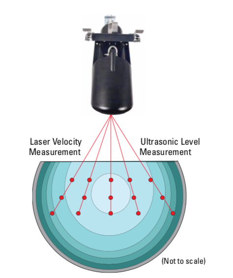 |
| Figure 2: Multi-point/Multi-depth velocity method. |
Sludge buildup at the bottom of the channels and high sediment concentration in the flow streams were the major problems for continuous flow rate measurement. The performance of submersible, continuous wave Doppler sensors, previously installed at the site, had been adversely affected by site conditions and required costly maintenance.
Finding the Solution with LaserFlow
The Teledyne Isco distributor recommended using the non-contact LaserFlow sensor at the site. The conditions at the bottom of the channels were less than ideal for traditional flow monitoring. Being placed over the channel LaserFlow overcomes this. First, the unit’s built-in ultra-sonic level transducer determines the stream’s level. This is done by emitting an ultrasonic pulse and measuring the time it takes for the echo to return from the stream’s surface. By using ultrasonic level measurement the sensor can calculate a subsurface point at which to focus an optical laser. The frequency shift (Doppler shifting) of the returned light from the laser is proportionate to the water’s velocity. LaserFlow is able to measure velocities at up to fifteen points below the water’s surface. Being able to measure at multiple points minimizes the effects of turbulence and eliminates the need for manual profiling. Above average results are achieved by producing a level measurement and an exceptionally accurate mean velocity reading.
Measuring Results and Feedback
 |
| Figure 3: Flow Rate Measuring Results for four inlet channels in dry weather conditions. |
Thanks to its non-contact technology for velocity and level measurement, the Signature configured with a LaserFlow was capable of providing consistent and continuous flow rate results (Figure 3).
The end-user was able to reduce costs of service by limiting site visits to periodic inspections of the LaserFlow without the need for stopping flow, entering into the manhole and/or cleaning the sensors.
For more information, contact Instrument Specialties, Inc. by calling 407-324-7800 or visiting http://isi.group.

How to Zero and Span the SOR 815DT Smart Differential Pressure Transmitter
 The SOR 815DT smart differential pressure transmitter is a rugged, compact, light weight, loop powered instrument that is ideally suited for hazardous locations and hostile environments where space is limited. The 815DT offers many industry standard outputs to meet applications where low cost, discrete and continuous monitoring is required or preferred. This versatile instrument may be used to reliably measure differential pressure, level or flow.
Zero and Span
- The 815DT has the ability to easily set the zero and span set points with a magnet externally.
- Located on the casting is a circle for zero and a triangle for span.
- To set the zero, bring the pressure to the desired value, and touch the magnet to the circle for 3 seconds.
- This will set the current pressure to zero.
- This is the same process for setting the span.
- Also, by holding the magnet to the circle and triangle at the same time, you will enter a test mode.
http://isi.group
407-324-7800
Applying Electric Valve Actuators: Needs Assessment
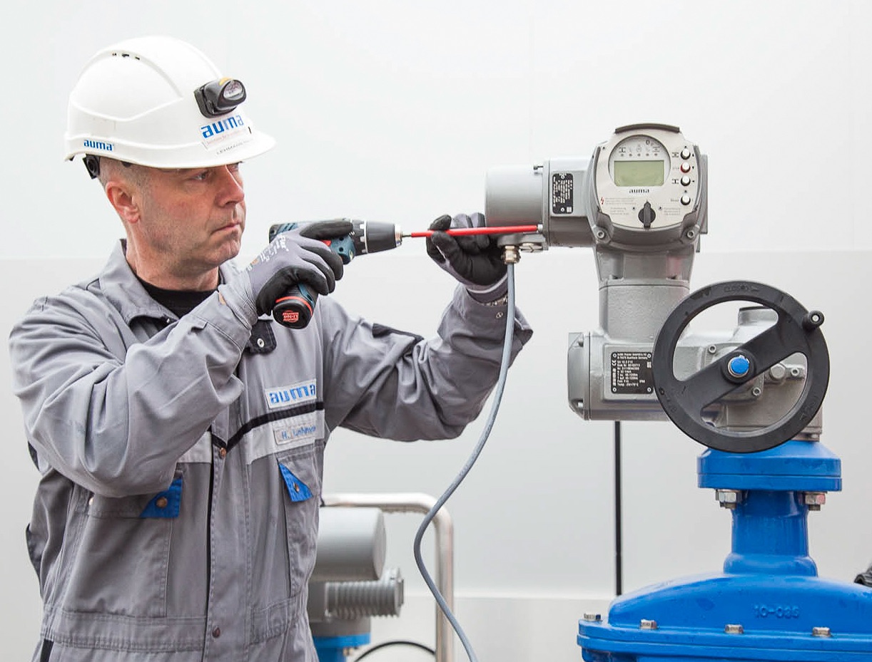 |
| Electric valve actuator (AUMA) |
Defined as an explicit set of requirements to be satisfied by a material, product, or service, engineers, during this step, will specify what the solution will accomplish, without describing how it will do it. Specifications usually originate from either design constraints or functional requirements.
As part of the spec requirements and need assessment, these are a number of the questions that engineers should consider, as early in the process as possible, in assessing the needs for a valve actuator.
- What sort of valve will be needed? Does the process require linear control valves or rotary quarter turn valves? This will define the appropriate type of actuator, as well.
- What is the specification for the actuator sizing? The size will need to match the needed thrust and torque as well as the type of valve. The efficient actuator, to ensure good valve control, can be neither oversized nor undersized.
- What are the power requirements, e.g. how much energy will be needed to run the actuator? Higher voltage actuators use more energy. Low power requirements mean that backup power is more economical. In most settings, there is a need to save money by running as efficiently as possible, and there are also environmental sustainability hurdles.
- Operating Conditions: Is there severe weather or will the actuator be under water? What is the range of temperatures expected? Keep in mind that not all actuators can work in all conditions.
- Will the actuator need to run continuously or intermittently? Consider the variation needed in the process. Actuators that have continual modulation are more able to respond to variations in the control requests.
- Consideration of environmental safety conditions. What about dust or explosive gases?
For more information on specifying electric valve actuators, contact Instrument Specialties by calling 407-324-7800 or visit their web site at http://isi.group

Temperature Sensors from SOR

All RTDs are 100% tested to insure that the accuracy and the continuity of the product have not been affected by the manufacturing process. The standard sheath material on all RTDs specified in this section is 316SS. Other sheath materials and coatings are available.
All industrial thermocouples are manufactured using a high purity mineral oxide insulation and a metallic sheath. The standard sheath material unless otherwise noted is 316SS.
Review the embedded catalog below, or download you own SOR Temperature Sensor Catalog from this link.
High Velocity Flow Monitoring in a Sanitary Sewer
 |
| View of flow inside the pipe. |
The alternate flow monitoring location was upstream, in a 42 inch pipe, and on the side of a hill. The level, which is 1-3 inches deep with velocity of 4.5 ft/s, was an additional challenge. Standard in-pipe area velocity sensors are not able to operate in conditions where high velocity effects the depth of the water accelerating over the top of the sensor (Bernoulli Effect) resulting in lower recorded levels.
 |
| Chart of the sensors output (click for larger view) |
The solution in this application was LaserFlow. LaserFlow uses a non-contact sensor that utilizes a non-contact ultrasonic level sensor and a laser to read the velocity below the surface. In this application the LaserFlow allowed for accurate readings to be taken even in the most turbulent of flows.
After the initial setup the LaserFlow sensor worked well for several hours. When the level decreased, the laser started to focus on the bottom of the channel due to the steep slope of the pipe. There were two options to correct this issue:
 |
| Flow Meter technician in the pipe adjusting the LaserFlow. |
- Send a technician back into the confined space to position the LaserFlow sensor parallel with the flow stream.
- Change the slope programming setting to match the slope of the pipe without having to enter into the confined space.
For more information about the Teledyne ISCO LaserFlow, contact Instrument Specialties, Inc. by visiting http://isi.group or by calling 407-324-7800.
Subscribe to:
Posts (Atom)