Showing posts with label flow measurement. Show all posts

Measuring Flow in Open Channels: Weirs, Flumes, Rivers & Streams


This video helps you find the best solution to your open channel flow issues. Whether your flow challenge be a flume, weir, river or stream, this presentation by Business Development Manager at Teledyne ISCO, Darrell Kuta, provides expert tips on how to overcome them.

Teledyne ISCO manufactures a wide range of products for professionals working in water pollution monitoring and abatement, engineers and managers involved with wastewater process control. They maintain an outstanding library of educational videos videos here: https://www.youtube.com/channel/UCtcYqTAaloE2TBoEkWeIMTA.

For more information about Teledyne ISCO products in Florida or the Caribbean contact Instrument Specialties by calling 407-324-7800  or visit their website at http://isi.group.

Influent Flow Monitoring at Wastewater Treatment Plant

Influent Flow Monitoring
Figure 1: Signature flow meter  with LaserFlow
sensor sheltered in weather enclosure.
Four Teledyne ISCO Signature Flow Meters, each configured with 360 LaserFlow sensors, were installed at the inlet of a very large wastewater treatment plant (WWTP). This flow monitoring technology provided a unique solution for the challenging flow conditions at this site. Non-contact Doppler laser technology was chosen by the user for their continuous and maintenance free flow monitoring.

Inlet Section Overview

Flow monitoring in the wastewater treatment process is key for verifying performance of the plant as a whole, as well as its individual processing sections. Due to the enormity of the plant’s processing capacity sewage streams are transferred to the plant through different main sewers, which merge into four rectangular inlet channels, each with a width of 1.5 m. At this location, the Signature flow meters and their non-contact LaserFlow sensors were installed over each of four inlet channels and sheltered in all-weather enclosures (Figure1).

Influent Flow Monitoring
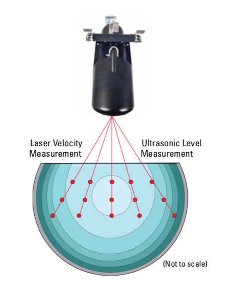
Figure 2: Multi-point/Multi-depth velocity method.
Site Challenges

Sludge buildup at the bottom of the channels and high sediment concentration in the flow streams were the major problems for continuous flow rate measurement. The performance of submersible, continuous wave Doppler sensors, previously installed at the site, had been adversely affected by site conditions and required costly maintenance.

Finding the Solution with LaserFlow

The Teledyne Isco distributor recommended using the non-contact LaserFlow sensor at the site. The conditions at the bottom of the channels were less than ideal for traditional flow monitoring. Being placed over the channel LaserFlow overcomes this. First, the unit’s built-in ultra-sonic level transducer determines the stream’s level. This is done by emitting an ultrasonic pulse and measuring the time it takes for the echo to return from the stream’s surface. By using ultrasonic level measurement the sensor can calculate a subsurface point at which to focus an optical laser. The frequency shift (Doppler shifting) of the returned light from the laser is proportionate to the water’s velocity. LaserFlow is able to measure velocities at up to fifteen points below the water’s surface. Being able to measure at multiple points minimizes the effects of turbulence and eliminates the need for manual profiling. Above average results are achieved by producing a level measurement and an exceptionally accurate mean velocity reading.

Measuring Results and Feedback
Influent Flow Monitoring
Figure 3: Flow Rate Measuring Results for four
inlet channels in dry weather conditions.

Thanks to its non-contact technology for velocity and level measurement, the Signature configured with a LaserFlow was capable of providing consistent and continuous flow rate results (Figure 3).

The end-user was able to reduce costs of service by limiting site visits to periodic inspections of the LaserFlow without the need for stopping flow, entering into the manhole and/or cleaning the sensors.

For more information, contact Instrument Specialties, Inc. by calling  407-324-7800 or visiting http://isi.group.

High Velocity Flow Monitoring in a Sanitary Sewer

View of flow inside the pipe
View of flow inside the pipe.
A sanitary sewer within a local municipality had two options for flow monitoring applications. The first application was in front of an overflow bypass gate where standard area velocity flow monitoring technologies were installed and working, but only intermittently. When the gate closed, the water surcharged the pipe until it overflowed into the bypass weir. The AV sensor was no longer able to read the bypass flow because the water at the bottom of the channel was no longer flowing. Another challenge was with the pipe joints creating turbulence.

The alternate flow monitoring location was upstream, in a 42 inch pipe, and on the side of a hill. The level, which is 1-3 inches deep with velocity of 4.5 ft/s, was an additional challenge. Standard in-pipe area velocity sensors are not able to operate in conditions where high velocity effects the depth of the water accelerating over the top of the sensor (Bernoulli Effect) resulting in lower recorded levels.
Chart of the sensors output
Chart of the sensors output (click for larger view)

The solution in this application was LaserFlow. LaserFlow uses a non-contact sensor that utilizes a non-contact ultrasonic level sensor and a laser to read the velocity below the surface. In this application the LaserFlow allowed for accurate readings to be taken even in the most turbulent of flows.

After the initial setup the LaserFlow sensor worked well for several hours. When the level decreased, the laser started to focus on the bottom of the channel due to the steep slope of the pipe. There were two options to correct this issue:
Flow Meter technician in the pipe adjusting the LaserFlow
Flow Meter technician in the pipe
adjusting the LaserFlow.
  • Send a technician back into the confined space to position the LaserFlow sensor parallel with the flow stream. 
  • Change the slope programming setting to match the slope of the pipe without having to enter into the confined space.
It was decided the slope setting would be changed. After determining the slope of the pipe from a 12 foot rise over a 150 foot run =8% slope. After a few program adjustments, the sensor worked flawlessly.


For more information about the Teledyne ISCO LaserFlow, contact Instrument Specialties, Inc. by visiting http://isi.group or by calling 407-324-7800.

Flumes For Water System Open Channel Flow Measurement

fiberglass cutthroat flume open channel flow measurement
This cutthroat flume is one of several types of flumes
used to facilitate open channel flow measurement.
Image courtesy Tracom Fiberglass Products
The measurement of flowing water in an open channel can be facilitated by applying known methodologies and a specifically shaped restriction in the flow path. The restriction is called a flume.

A flume, as applied to open channel flow, is a fixed structure in the flow path that directs or restricts the flowing water in a manner that allows a measurement of the fluid depth at a defined point to be translated into a volumetric flow rate. There are several different types of flumes, each with a characteristic measuring procedure used to determine flow volume. Applications for flumes and their open channel flow measurement techniques are commonly found in agriculture, sewer systems, water treatment, and industrial effluent measurement stations.

Flumes can provide measurement accuracy suitable for many uses. Advantages are their simplicity, ease of maintenance, comparatively small footprint, and ability to measure large flows. Fiberglass flumes provide solid long term performance due to their corrosion resistance and smooth, easy to maintain, surface. Prefabricated units can be shipped to an installation site and easy installed.

Share your open channel flow measurement challenges with application specialists, leveraging your own knowledge and experience with their product application expertise.

Vortex Flowmeters

vortex or multivariable flowmeter flow meter for process measurement
Multivariable vortex flowmeter combines flow, temperature
and pressure measurement into a single compact instrument
Image courtesy Krohne
Vortex shedding flowmeters provide process operators with consistent fluid flow rate measurements across a wide range of applications. These flowmeters measure the volumetric flow rate of steam, gas, and low viscosity liquids, boasting both versatility and dependability when used in conjunction with process systems.

Vortex shedding refers to the phenomenon wherein flowing gas or liquid form vortices around a solid object placed in the flow path. The measurement technology returns an indication of the process fluid velocity, which can then be used to provide volumetric or mass flow data. Vortex technology is well suited for many applications involving cryogenic liquids, hydrocarbons, air, and industrial gases. Vortex flow measurement requires contact between portions of the measurement instrument and the process media, so these flowmeters are commonly fashioned from a range of corrosion resistant materials.

The process of measuring the flow involves both the flowmeter and the ability for other instrumentation to measure the vortices themselves in order to calculate velocity. Ultrasonic sensors have become popular tools for measuring vortices. Applications involving flow measurement of high viscosity fluids are not suited for vortex technology because extremely viscous fluids do not behave in the same manner as lower viscosity fluids when their flow path is obstructed. Splitting higher viscosity fluids into concordant vertices is extremely difficult due to the internal friction present in highly viscous liquids.

Additionally, in order to split these process liquids, the piping through which the process material flows must be straight, and any disturbance or vibration in the pipe may impact the measurement. A vortex flowmeter will be in a fixed installation. This stationary element, operating without electrodes, can be advantageous for flow measurement in chemical applications utilizing low viscosity fluids.

The vortex shedding flowmeter is widely used for the measurement of steam flow. The high pressure and elevated temperature of steam, along with the variation that exists in most steam systems, have little negative impact on the operation of a vortex flowmeter. Vortex shedding flowmeters are often volumetrically based in terms of measurement, but their output can be combined with other fluid information to calculate mass flow. A product variant commonly available will combine the vortex flow measurement with temperature and pressure compensation, delivering three process measurements from a single installed device.

Share your process and flow measurement challenges with instrumentation specialists, leveraging your own knowledge and experience with their product application expertise.

Ultrasonic Flow Measurement Overview

ultrasonic flowmeter for custody transfer
One of several versions of ultrasonic flowmeter suitable
for custody transfer operations.
Courtesy Krohne
Ultrasonic flow meters measure, via sound waves inaudible to humans, the velocity of fluid flowing through a conduit. The conduit can be a recognizable closed piping run, or open channels, flumes, or chutes. The technology is predominantly applied to liquids and gases. 

There are three types of ultrasonic flow meters, differentiated by their means of measurement. An open channel flow meter derives liquid depth by computing geometrical distance, combining it with a velocity measurement and known dimensional properties of a flume or other channel. A Doppler shift flow meter reflects ultrasonic energy off sonically reflective materials and measures the frequency shift between emission and reflection to derive a fluid velocity measurement. The contrapropogating transit-time flow meter, more recognizably, the transmission flow meter. The transmission flow meter has two versions: the in-line and the clamp-on. The in-line configuration is intrusive, with flow meter hardware extending into and exposed to the measured media. A clamp-on style ultrasonic flow meter resides on the outside of the pipe, emitting and receiving the ultrasonic pulses through the pipe wall. These process measurement tools, using ultrasound technology, have the ability to measure fluid velocity and calculate volumetric, mass, and totalized flow. The use of ultrasonic flow measurement is prevalent in the oil and gas, nuclear, wastewater, pharmaceutical, and food and beverage industries. It is also employed in energy management systems as a means to measure energy demand. 

For intrusive flow meters, sensors are fitted opposite one another and alternate bouncing ultrasonic signals back and forth in the pipe, in an almost tennis-like format. In an elementary explanation, by increasing the number of sensors, engineers are able to decipher flow proportions through calculations of velocity between sensory transmissions; thereby, the flow volume can be computed. 

For externally mounted flow meters, a clamp-on device affixes the flow meter measurement elements to the pipe. One special characteristic of clamp-on flow meters is the ability to transmit ultrasonic signals through piping up to four meters in diameter, making them suitable for application in very large systems such as those found in hydroelectric or wastewater installations. The clamp-on arrangement also facilitates addition of a flow measurement point to an existing system without process interruption. 

The technology is pervasive in the processing industries, having its particular niche of applications where it excels. Proper installation is a key element in producing reliable and consistent results. Ultrasonic energy flow technology is used for custody transfer of natural gases and petroleum liquids. Custody transfer usually entails following industry, national, and government standards and regulations. Other popular applications include compressed air system monitoring and energy usage metering. 

Ultrasonic flow meters, with no moving parts, are comparatively low maintenance and self-diagnosing. Temperature and pressure measurements are needed to calculate mass flow of gases. When measuring liquid mass flow in pipes, it is generally necessary for the pipe cross section to be media filled in order to obtain reliable results. 

Whatever your flow measurement challenge, share it with a process measurement specialist. Combine your process knowledge with their product application expertise to develop effective solutions.

Open Channel Flow Measurement Combines Laser and Ultrasonic Technologies


Combining Doppler laser velocity measurement with ultrasonic level measurement enables the Teledyne ISCO LaserFlow™ sensor to provide reliable and accurate flow measurement in open channel applications.

Ultrasonic technology is used to determine the depth of the liquid stream and identify a sub-surface point at which to measure velocity. After focusing the sensor's laser on the target, Doppler shift in the returned light is used to calculate the flow velocity. A flow computer combines the information to produce useful flow data.

The video provides detail on the application and features of the LaserFlow™ sensor. Share your flow measurement requirements and challenges with instrumentation specialists, combining your own process knowledge and experience with their product application expertise to develop effective solutions.