An informational site dedicated to process control education. Posts on this blog contain interesting and noteworthy information about process instrumentation, valves, and equipment used in industrial and municipal facilities. This blog is sponsored by Instrument Specialties, Inc. (ISI). For more information, please visit ISI.GROUP
Showing posts with label differential pressure. Show all posts
The SOR815DT smart differential pressure transmitter is a rugged, compact, light weight, loop powered instrument that is ideally suited for hazardous locations and hostile environments where space is limited. The 815DT offers many industry standard outputs to meet applications where low cost, discrete and continuous monitoring is required or preferred. This versatile instrument may be used to reliably measure differential pressure, level or flow.
Zero and Span
The 815DT has the ability to easily set the zero and span set points with a magnet externally.
Located on the casting is a circle for zero and a triangle for span.
To set the zero, bring the pressure to the desired value, and touch the magnet to the circle for 3 seconds.
This will set the current pressure to zero.
This is the same process for setting the span.
Also, by holding the magnet to the circle and triangle at the same time, you will enter a test mode.
Differential pressure transmitters are utilized in the process control industry to represent the difference between two pressure measurements. One of the ways in which differential pressure (DP) transmitters accomplish this goal of evaluating and communicating differential pressure is by a process called inferential measurement. Inferential measurement calculates the value of a particular process variable through measurement of other variables which may be easier to evaluate. Pressure itself is technically measured inferentially. Thanks to the fact numerous variables are relatable to pressure measurements, there are multiple ways for DP transmitters to be useful in processes not solely related to pressure and vacuum.
An example of inferential measurement via DP transmitter is the way in which the height of a vertical liquid column will be proportional to the pressure generated by gravitational force on the vertical column. The differential pressure transmitter measures the pressure exerted by the contained liquid. That pressure is related to the height of the liquid in the vessel and can be used to calculate the liquid depth, mass, and volume. The gravitational constant allows the pressure transmitter to serve as a liquid level sensor for liquids with a known density. A true differential pressure transmitter also enables liquid level calculations in vessels that may be pressurized.
Gas and liquid flow are two common elements maintained and measured in process control. Fluid flow rate through a pipe can be measured with a differential pressure transmitter and the inclusion of a restricting device that creates a change in fluid static pressure. In this case, the pressure in the pipe is directly related to the flow rate when fluid density is constant. A carefully machined metal plate called an orifice plate serves as the restricting device in the pipe. The fluid in the pipe flows through the opening in the orifice plate and experiences an increase in velocity and decrease in pressure. The two input ports of the DP transmitter measure static pressure upstream and downstream of the orifice plate. The change in pressure across the orifice plate, combined with other fluid characteristics, can be used to calculate the flow rate.
Process environments use pressure measurement to inferentially determine level, volume, mass, and flow rate. Using one measurable element as a surrogate for another is a useful application, so long as the relationship between the measured property (differential pressure) and the inferred measurement (flow rate, liquid level) is not disrupted by changes in process conditions or by unmeasured disturbances. Industries with suitably stable processes - food and beverage, chemical, water treatment - are able to apply inferential measurement related to pressure and a variable such as flow rate with no detectable impact on the ability to measure important process variables.
* Image courtesy of T. Kuphaldt and his book "Lessons In Industrial Instrumentation"
In a fluid system, differential pressure measurement can be utilized in conjunction with a known restrictive element in the flow path to produce a flow measurement. Manufacturers of process measurement and control apparatus often produce application notes that reflect their experience or knowledge about specific circumstances that may create problems for users and operators. The application notes outline the circumstances that create the potential for trouble, then go on to show a method of prevention, mitigation, or elimination of the problem condition.
Brooks Instrument, globally recognized innovator in precision measurement and control of flow and pressure, has produced an application note that deals with differential pressure transmitter sensor lines and how to prevent them from being fouled by accumulation of media residue. The application note is included below and also appears in the Brooks Instrument blog.
Share your process measurement challenges and requirements with product application specialists, combining your own process knowledge and experience with their product application expertise to develop effective solutions.
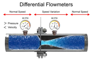
The differential flow meter is the most common device for measuring fluid flow through pipes. Flow rates and pressure differential of fluids, such as gases vapors and liquids, are explored using the orifice plate flow meter in the video below.
The differential flow meter, whether Venturi tube, flow nozzle, or orifice plate style, is an in line instrument that is installed between two pipe flanges.
The orifice plate flow meter is comprised the circular metal disc with a specific hole diameter that reduces the fluid flow in the pipe. Pressure taps are added on each side at the orifice plate to measure the pressure differential.
According to the Laws of Conservation of Energy, the fluid entering the pipe must equal the mass leaving the pipe during the same period of time. The velocity of the fluid leaving the orifice is greater than the velocity of the fluid entering the orifice. Applying Bernoulli's Principle, the increased fluid velocity results in a decrease in pressure.
As the fluid flow rate increases through the pipe, back pressure on the incoming side increases due to the restriction of flow created by the orifice plate.
The pressure of the fluid at the downstream side at the orifice plate is less than the incoming side due to the accelerated flow.
With a known differential pressure and velocity of the fluid, the volume metric flow rate can be determined. The flow rate “Q”, of a fluid through an orifice plate increases in proportion to the square root the pressure difference on each side multiplied by the K factor. For example if the differential pressure increases by 14 PSI with the K factor of one, the flow rate is increased by 3.74.