Showing posts with label level measurement. Show all posts

Instrumentation and Plant Safety Case Study: Refinery Explosion


A case study of the 2005 BP refinery explosion in Texas City, TX. This video recaps the events and circumstances leading up to a catastrophic explosion. Contributing factors include inadequate level and safety instrumentation, as well as breakdowns in safety monitoring and standard operating procedures. This video, courtesy of the Chemical Safety Board (csv.gov) is an excellent educational reference and should be viewed by engineering, maintenance, and plant management personnel everywhere.

Instrument Specialties, Inc.
http://isi.group
407-324-7800

Influent Flow Monitoring at Wastewater Treatment Plant

Influent Flow Monitoring
Figure 1: Signature flow meter  with LaserFlow
sensor sheltered in weather enclosure.
Four Teledyne ISCO Signature Flow Meters, each configured with 360 LaserFlow sensors, were installed at the inlet of a very large wastewater treatment plant (WWTP). This flow monitoring technology provided a unique solution for the challenging flow conditions at this site. Non-contact Doppler laser technology was chosen by the user for their continuous and maintenance free flow monitoring.

Inlet Section Overview

Flow monitoring in the wastewater treatment process is key for verifying performance of the plant as a whole, as well as its individual processing sections. Due to the enormity of the plant’s processing capacity sewage streams are transferred to the plant through different main sewers, which merge into four rectangular inlet channels, each with a width of 1.5 m. At this location, the Signature flow meters and their non-contact LaserFlow sensors were installed over each of four inlet channels and sheltered in all-weather enclosures (Figure1).

Influent Flow Monitoring
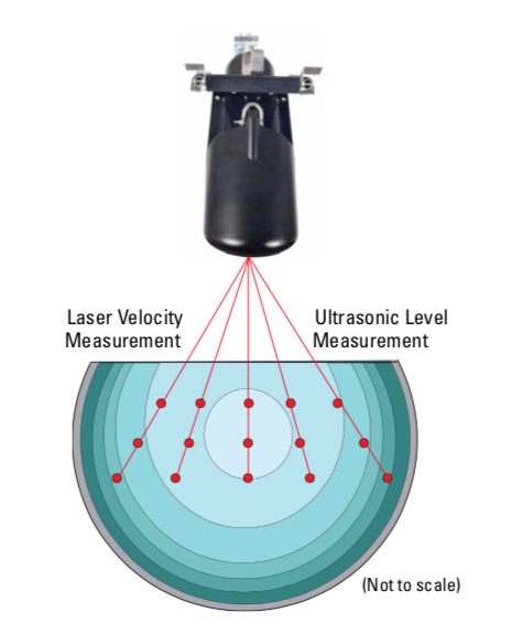
Figure 2: Multi-point/Multi-depth velocity method.
Site Challenges

Sludge buildup at the bottom of the channels and high sediment concentration in the flow streams were the major problems for continuous flow rate measurement. The performance of submersible, continuous wave Doppler sensors, previously installed at the site, had been adversely affected by site conditions and required costly maintenance.

Finding the Solution with LaserFlow

The Teledyne Isco distributor recommended using the non-contact LaserFlow sensor at the site. The conditions at the bottom of the channels were less than ideal for traditional flow monitoring. Being placed over the channel LaserFlow overcomes this. First, the unit’s built-in ultra-sonic level transducer determines the stream’s level. This is done by emitting an ultrasonic pulse and measuring the time it takes for the echo to return from the stream’s surface. By using ultrasonic level measurement the sensor can calculate a subsurface point at which to focus an optical laser. The frequency shift (Doppler shifting) of the returned light from the laser is proportionate to the water’s velocity. LaserFlow is able to measure velocities at up to fifteen points below the water’s surface. Being able to measure at multiple points minimizes the effects of turbulence and eliminates the need for manual profiling. Above average results are achieved by producing a level measurement and an exceptionally accurate mean velocity reading.

Measuring Results and Feedback
Influent Flow Monitoring
Figure 3: Flow Rate Measuring Results for four
inlet channels in dry weather conditions.

Thanks to its non-contact technology for velocity and level measurement, the Signature configured with a LaserFlow was capable of providing consistent and continuous flow rate results (Figure 3).

The end-user was able to reduce costs of service by limiting site visits to periodic inspections of the LaserFlow without the need for stopping flow, entering into the manhole and/or cleaning the sensors.

For more information, contact Instrument Specialties, Inc. by calling  407-324-7800 or visiting http://isi.group.

Continuous Liquid Level Measurement Technologies Used in Industry

differential pressure transmitter for industrial process control
Industrial differential pressure transmitter
Courtesy Krohne
Although continuous level measurement technologies have the ability to quantify applications for bulk solids, slurries, and granular materials, this article will focus on level measurement technologies applied to liquid level measurement utilized in process control. A distinction should be made between continuous level measurement and point level measurement. Point level measurement acts like a switch, changing state when a single level condition is achieved. Called “transmitters,” continuous liquid level measurement devices employ technologies ranging from hydrostatics to magnetostriction, providing uninterrupted signals that indicate the level of liquid in a vessel, tank, or other container.

Hydrostatic devices focus on the equilibrium of dynamic and static liquids. There are three main types of hydrostatic transmitters: 1) displacer, 2) bubbler, and 3) differential pressure.

The displacer transmitters utilize a float placed within the liquid container. With its buoyancy characterized to the liquid and the application, the float, a connecting stem, and a range spring or similar counterbalance represents the liquid level in terms of the movement of the displacer (float). The displacement, or movement, of the assembly is converted into an electric signal for use by the monitoring and control system.

Bubbler transmitters are used for processing vessels that operate at atmospheric pressure. This method introduces a purge gas or an inert gas, e.g. air or dry nitrogen, into a tube extending into the liquid vessel. Precise measurement of the pressure exerted on the gas in the dip tube by the liquid in the tank is used to determine the height of the liquid.

Differential pressure (DP) transmitters rely directly on, in a basic explanation, the pressure difference between the bottom and top of the container. Precise pressure measurement is used to determine the height of the liquid in the tank. One of the most advantageous aspects of DP transmitters is that they can be used in pressurized containers.

Other examples of level transmitter technologies which are not hydrostatic devices include magnetostrictive, capacitance, ultrasonic, laser, and radar.

In magnetostrictive level transmitters the measuring device, a float, has a magnet that creates a magnetic field around a wire enclosed in a tube. Electrical pulses sent down the wire by the transmitter head produce a torsional wave related to the position of the float, which moves with changes in liquid surface level. The transit time of the torsion wave back to the sensing head is measured and the depth of the liquid, as indicated by the float position, can be determined.

Capacitance transmitters are best applied to liquids that have high dielectric constants. Essentially, changes in the capacitance of the sensor / tank / liquid assembly will vary proportionately with the liquid level. The change in capacitance is measured and converted to an appropriate electrical signal.

Ultrasonic level transmitters emit ultrasonic energy from the top of the vessel toward the liquid. The emissions are reflected by the liquid surface and them time required for the signal to return to the source is used to determine the distance to the liquid surface.

Laser level transmitters operate similarly to an ultrasonic level transmitter. However, instead of using ultrasound signals, they use pulses of light.

Radar level transmitters involve microwaves emitting downward from the top of the container to the liquid’s surface. The measured time for receipt of a return sign reflecting off the liquid surface enables calculation of the distance from the sensor to the liquid surface.

The precise measurement of transmit time for a wave or pulse of energy is employed in several of the technologies, the measurement of pressure in others. Each technology has a set of attributes making it an advantageous selection for a particular range of applications. Various manufacturers offer modified or enhanced versions of the basic measurement technologies to provide performance or cost benefits for ranges of applications. Share your liquid level measurement challenges with an application expert, combining you process knowledge with their product application expertise to develop effective solutions.

Summary of Technologies Used For Continuous Liquid Level Measurement in Industrial Process Control

radar level transmitter
Two versions of radar level transmitters
Courtesy Krohne
Automated liquid processing operations in many fields have requirements for accurate and reliable level measurement. The variety of media and application criteria demand continuous improvement in the technology, while still retaining niches for older style units utilizing methods that, through their years of reliable service, inspire confidence in operators.

Here is a synopsis of the available technologies for instruments providing continuous liquid level measurement. All are generally available in the form of transmitters with 4-20 mA output signals, and most are provided with additional outputs and communications. What is notably not covered here are level switches or level gauges that do not deliver a continuous output signal corresponding to liquid level.

Whether considering a new installation or upgrading an existing one, it can be a good exercise to review several technologies as possible candidates for a project. None of the technologies would likely be considered the best choice for all applications. Evaluating and selecting the best fit for a project can be facilitated by reaching out to a product application specialist, sharing your applications challenges and combining your process knowledge with their product expertise to develop an effective solution.

Displacer – A displacer is essentially a float and a spring that are characterized for a particular liquid and range of surface level movement. The displacer moves in response to liquid level, changing the location of a core connected to the displacer by a stem. The core is within a linear variable differential transformer. The electrical output of the transformer changes as the core moves.

Guided Wave Radar – A radar based technology that uses a waveguide extending into the liquid. The radar signal travels through the waveguide, basically a tube. The liquid surface level creates a dielectric condition that generates a reflection. Calculations and processing of the emitted and returned signals provide a measure of distance to the liquid surface. No moving parts.

Magnetostrictive – A method employing measurement of the transit time of an electric pulse along a wire extending down an enclosed tube oriented vertically in the media. A magnetic float on the exterior of the tube moves with the liquid surface. The float’s magnetic field produces the return signal to the sensor. Processing the time from emission to return provides a measure of distance to the liquid surface.

Pulse Burst Radar - A radar based technology employing emissions in precisely timed bursts. The emission is reflectex from the liquid surface and transit time from emission to return is used to determine distance to media surface.  Not adversely impacted by changes in media conductivity, density, pressure, temperature. No moving parts.

Frequency Modulated Continuous Wave Radar – Another radar based technology that employs a radar signal that sweeps linearly across a range of frequencies. Signal processing determines distance to media surface.  Not adversely impacted by changes in media conductivity, density, pressure, temperature. No moving parts.

RF Capacitance - As media rises and falls in the tank, the amount of capacitance developed between the sensing probe and the ground reference (usually the side metal sidewall) also rises and falls. This change in capacitance is converted into a proportional 4-20 mA output signal. Requires contact between the media and the sensor, as well as a good ground reference. No moving parts.

Ultrasonic Non-Contact – Ultrasonic emission from above the liquid is reflected off the surface. The transit time between emission and return are used to calculate the distance to the liquid surface. No contact with media and no moving parts.

Differential Pressure – Pressure sensor at the bottom of a vessel measures the pressure developed by the height of the liquid in the tank. No moving parts. A variation of this method is often called a bubbler, which essentially measures hydrostatic pressure exerted on  the gas in a tube extending into the contained liquid. It has the advantage of avoiding contact between the measuring instrument parts, with the exception of the dip tube, and the subject liquid.

Laser - Probably one of the latest arrivals on the liquid level measurement scene, laser emission and return detection is used with time interval measuring to accurately determine the distance from the sensor source to the liquid surface.

Load Cell - A load cell or strain gauge can be incorporated into the support structure of the liquid containing vessel. Changes in the liquid level in the vessel are detected as distortions to the structure and converted, using tank geometry and specific gravity of the liquid.

All of these technologies have their own set of attributes which may make them more suitable to a particular range of applications. Consulting with a product specialist will help determine which technologies are the best fit for your application.