Measuring Flow in Open Channels

Parshall flume at a water treatment facility
Courtesy Tracom Fiberglass Products
Industrial, municipal, and commercial processing operations can employ open channels as a means to direct and transport liquids. Open channel flow is technically fluid passing through a conduit with a free surface. The mechanics of this type of flow are well characterized, allowing volumetric flow rate to be determined using a single measurement of liquid depth as it passes through a channel of known shape. These shaped portions of the fluid transport system are known as flumes.

There are a number of different flume types used for flow measurement, each with its own name, shape, and application characteristics. One of the most common is the Parshall flume, named after its inventor. In its simplest application, the Parshall flume directs liquid flow through a narrowed throat. The depth of the liquid is measured at a designated point along the flume. Using known flow characteristics for the flume shape and size, volumetric flow rate can be calculated using the depth measurement.

Flumes are widely used in wastewater treatment plants, irrigation, and other applications where flow measurement is needed in an open channel. The flume can be constructed of almost any suitable material, but must be dimensionally correct and stable. Fiberglass is often a material of choice because of its weight, corrosion resistance, cost, and ease of installation. A fiberglass flume can be prefabricated with dimensional precision, shipped to the installation site and essentially dropped in place as a complete unit. Numerous options are available with fiberglass flumes to accommodate every installation requirement.
  • Ultrasonic level sensor mounting brackets
  • Bubble tubes
  • Sample tubes
  • Submerged probe cavities
  • Stilling wells (attached and detached)
  • Staff gauges
  • Removable probe holders
  • Inlet and outlet end adapters
  • Pipe stubs
  • Flanged end connections
  • Flow straighteners
  • Fiberglass grating
  • Inlet and outlet wingwalls
  • Multi-piece construction
  • Nesting
  • Chemically resistant gel coal
Share your open channel flow measurement challenges and requirements with an application specialist for recommendations on complete flow measurement solutions.

Combating Cavitation in Industrial Process Control Valves

bubbles resulting from cavitation
Cavitation in liquid processes produces bubbles which can
damage valves.
In process control valves, cavitation results from a rapid drop in pressure as liquid passes through the valve. It results in the formation of vapor spaces or bubbles within the valve cavity. When the bubbles move downstream into a larger cross-sectional area, velocity decreases and pressure increases. The higher pressure now surrounding the bubbles causes them to implode, producing shockwaves which propagate through the liquid. These shockwaves can cause metal fatigue and excessive wear on the internals of the valve. The collapsing bubbles also make a discernible sound with accompanying vibration. The cumulative effects of cavitation can cause rapid deterioration of a valve, resulting in reduced control function, frequent need for service, or premature failure.

There are ways to mitigate cavitation. Some involve changes in the process, others, incorporating a properly designed and selected valve with trim that reduces or prevents the conditions that cause cavitation. The paper below, authored by Flowserve, provides an in depth examination of the causes of cavitation, then continues with explanation of how their specialty valves are designed to overcome the conditions that promote it.

There are detailed illustrations showing the specific valve trim features that impede cavitation. Share your process control valve challenges with application experts, combining your process knowledge with their product application expertise to develop effective solutions.


Computational Fluid Dynamics Applied to Effective In-Tank Mixing


Jacoby Tarbox uses computational fluid dynamics software to reliably and predictably model the performance of their eductors used to accomplish mixing in tanks, open vessels, and other containers. The video provides an overview of how the company determines the arrangement of eductors that will provide the mixing performance required by each customer.

Share your interest or application challenges with a product application specialist, combining your process knowledge with their product application expertise to develop effective solutions.

Achieving Close Control of Process Temperature

industrial temperature transmitter sensor with flange mount
Temperature sensor type, construction, and
location contribute to system performance
Courtesy Krohne
Temperature control is a common operation in the industrial arena. Its application can range across solids, liquids, and gases. The dynamics of a particular operation will influence the selection of instruments and equipment to meet the project requirements. In addition to general performance requirements, safety should always be a consideration in the design of a temperature control system involving enough energy to damage the system or create a hazardous condition.

Let's narrow the application range to non-flammable flowing fluids that require elevated temperatures. In the interest of clarity, this illustration is presented without any complicating factors that may be encountered in actual practice. Much of what is presented here, however, will apply universally to other scenarios.
What are the considerations for specifying the right equipment?
KNOW YOUR FLOW

First and foremost, you must have complete understanding of certain characteristics of the fluid.

  • Specific Heat - The amount of heat input required to increase the temperature of a mass unit of the media by one degree.
  • Minimum Inlet Temperature - The lowest media temperature entering the process and requiring heating to a setpoint. Use the worst (coldest) case anticipated.
  • Mass Flow Rate - An element in the calculation for total heat requirement. If the flow rate will vary, use the maximum anticipated flow.
  • Maximum Required Outlet Temperature - Used with minimum inlet temperature in the calculation of the maximum heat input required.

MATCH SYSTEM COMPONENT PERFORMANCE WITH APPLICATION

  • Heat Source - If temperature control with little deviation from a setpoint is your goal, electric heat will likely be your heating source of choice. It responds quickly to changes in a control signal and the output can be adjusted in very small increments to achieve a close balance between process heat requirement and actual heat input.
  • Sensor - Sensor selection is critical to attaining close temperature control. There are many factors to consider, well beyond the scope of this article, but the ability of the sensor to rapidly detect small changes in media temperature is a key element of a successful project. Attention should be given to the sensor containment, or sheath, the mass of the materials surrounding the sensor that are part of the assembly, along with the accuracy of the sensor.
  • Sensor Location - The location of the temperature sensor will be a key factor in control system performance. The sensing element should be placed where it will be exposed to the genuine process condition, avoiding effects of recently heated fluid that may have not completely mixed with the balance of the media. Locate too close to the heater and there may be anomalies caused by the heater. A sensor installed too distant from the heater may respond too slowly. Remember that the heating assembly, in whatever form it may take, is a source of disturbance to the process. It is important to detect the impact of the disturbance as early and accurately as possible.
  • Controller - The controller should provide an output that is compatible with the heater power controller and have the capability to provide a continuously varying signal or one that can be very rapidly cycled. There are many other features that can be incorporated into the controller for alarms, display, and other useful functions. These have little bearing on the actual control of the process, but can provide useful information to the opeartor.
  • Power Controller - A great advantage of electric heaters is their compatibility with very rapid cycling or other adjustments to their input power. A power controller that varies the total power to the heater in very small increments will allow for fine tuning the heat input to the process.
  • Performance Monitoring - Depending upon the critical nature of the heating activity to overall process performance, it may be useful to monitor not only the media temperature, but aspects of heater or controller performance that indicate the devices are working. Knowing something is not working sooner, rather than later, is generally beneficial. Controllers usually have some sort of sensor failure notification built in. Heater operation can be monitored my measurement of the circuit current.

SAFETY CONSIDERATIONS

Any industrial heater assembly is capable of producing surface temperatures hot enough to cause trouble. Monitoring process and heater performance and operation, providing backup safety controls, is necessary to reduce the probability of damage or catastrophe.

  • High Fluid Temperature - An independent sensor can monitor process fluid temperature, with instrumentation providing an alert and limit controllers taking action if unexpected limits are reached.
  • Heater Temperature - Monitoring the heater sheath temperature can provide warning of a number of failure conditions, such as low fluid flow, no fluid present, or power controller failure. A proper response activity should be automatically executed when unsafe or unanticipated conditions occur.
  • Media Present - There are a number of ways to directly or indirectly determine whether media is present. The media, whether gaseous or liquid, is necessary to maintain an operational connection between the heater assembly and the sensor.
  • Flow Present - Whether gaseous or liquid media, flow is necessary to keep most industrial heaters from burning out. Understand the limitations and operating requirements of the heating assembly employed and make sure those conditions are maintained.
  • Heater Immersion - Heaters intended for immersion in liquid may have watt density ratings that will produce excessive or damaging element temperatures if operated in air. Strategic location of a temperature sensor may be sufficient to detect whether a portion of the heater assembly is operating in air. An automatic protective response should be provided in the control scheme for this condition.

Each of the items mentioned above is due careful consideration for an industrial fluid heating application. Your particular process will present its own set of specific temperature sensing challenges with respect to performance and safety. Share your requirements with temperature measurement and control experts, combining your process knowledge with their expertise to develop safe and effective solutions.

Video Shows How to Install a Portable Ultrasonic Clamp-on Flowmeter

portable ultrasonic flowmeter
Krohne Optisonic 6300 P
Portable Ultrasonic Flowmeter
Ultrasonic flowmeters, being capable of operating from outside a pipe, are well suited to field measurements and other portable applications in industrial process measurement. Krohne, a globally recognized manufacturer of flow, pressure, temperature, level, and other instruments for process measurement and control, has produced video instructions for field installation and operation of their portable ultrasonic clamp-on flowmeter. The video is included below. Though the presentation is based upon the Krohne product, there is good general knowledge about portable ultrasonic flowmeters to be had from the video.

Watch the video and build your knowledge. Share your process measurement challenges with application specialists, combining your process knowledge with their product application expertise to formulate effective solutions.


Application of Rugged Dump Valve and Liquid Level Control on Separator

Industrial process control valve with flange connections and pneumatic actuator
Model 1450 Valve
Courtesy SOR
SOR, a globally recognized manufacturer of measurement and control equipment and instruments, recently published an application note about the use of two of their products in combination.

The SOR® 1600 Series level controllers are designed for liquid level and interface control applications calling for either modified percent (throttling) or quick opening (snap) pneumatic service. The device is fully mechanical and provides a pneumatic output signal.

SOR's Model 1450 valve is a close-coupled control valve designed to meet pressure and erosive applications common to the oil and gas industry. The intended applications for the valves include controlling liquid level on 2 or 3 phase gas separators, gas dehydrators, compressors, scrubbers, heat treaters, well test systems, and other oil field equipment. Ease of maintenance, rugged steel construction, hardened trim, application flexibility, and a range of safety features are all designed into the product.

The application note illustrates how these two products provide control of a separator. Whatever your fluid process control application, share your challenges with process control specialists, combining your process knowledge with their product application expertise to develop effective solutions.

Cell Change Out On Siemens Air Cooled Drive


Part of a good design for industrial equipment is providing for effective maintenance and service with a minimal time commitment. In the video, you can see the procedure for change out of an internal cell on a Siemens Sinamic air cooled drive. The procedure, as you will see, is straight forward and takes little valuable time.

Share your drive component requirements and challenges with product experts, combining your facility and process knowledge with their product application expertise to develop effective solutions.

Installing Industrial Heat Trace Cable on Piping

Heat tracing of process piping is important to the successful maintenance or operation of systems containing heat sensitive fluids or installed in cold environments. Properly installing heat trace cable is essential to establishing effective and safe operation.

Raychem, a Pentair brand, provides an instructive video showing how to correctly install heating cables on the exterior of piping systems. Some of the content may be specific to Raychem products, but the general concepts have application to many installations and will help build knowledge and expertise.

Share your piping system heat trace requirements and challenges with a product expert, combining your process and facilities knowledge with their product application expertise to develop effective solutions.

Fixed Installation Gas Monitors for Industrial Safety

industrial hazardous gas monitor fixed installation
GAs monitor for industrial environments
MSA
MSA is the premier source for safety equipment, including permanently installed gas detectors to monitor levels of oxygen, combustibles, and toxic gases. The video below provides a complete overview of MSA's Ultima X line of gas monitors, including options and product variants.

Be mindful of the potential has hazards in your facility. Share your gas monitoring requirements and challenges with product specialists for assistance in matching the best product to your application.

Turbidity Meter - Hygienic for Food and Beverage Industry

continuous turbidity measurement instrument
Hygienic Turbidity Measurement Instrument
Krohne
Turbidity is a measurement related to the particle content of a fluid. While it does not provide a direct particle count, it does deliver an indication of the optical clarity of the liquid, with the measurement being proportional to particle content. This is important to food and beverage manufacturers in maintaining consistent levels of quality and product character.

A liquid processing industry, such as the food and beverage industry, can benefit from continuous monitoring of turbidity, as opposed to periodic sampling. The rate at which manufacturers process liquids generally negates the use of a sampling method due to the large amounts of material processed between sampling and the processing of their results. Continuous measurement provides the fastest response to any trending or immediate changes in the fluid character.

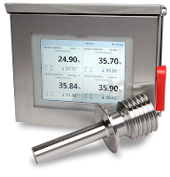
One instrument manufacturer, Krohne, provides hygienic turbidity meters that can be installed, inserted into a pipe or vessel, to provide continuous turbidity readings. The instrument utilizes a near infrared light source, which eliminates the impact of medium color on the measurement. Krohne delivers a measuring system for monitoring the optical density of absorption of fluids in order to monitor continuous process results or to securely indicate changes. The process instrument has the capability to calibrate itself, preserving its high level of accuracy. Analog and digital outputs provide connective pathways to monitoring and control systems, and a number of product variants accommodate ease of use and several measurement ranges.

More detail is provided below in the technical data sheet. Share you process instrumentation requirements and challenges with product application specialists, combining your process knowledge and experience with their product application expertise to develop effective solutions.


Use Electronic Pressure Controllers in Your Research Process Loop to Eliminate Droop, Boost, and Hysteresis

(re-blogged with permission from Brooks Instrument)

Gas pressure control is critical in many applications like life sciences and chemical/petrochemical research where flow is an integral part of the process. Brooks Instrument electronic pressure controllers can be used as they require flow to function. Compared to using a mechanical pressure regulator, electronic pressure controllers eliminate droop, boost and hysteresis, offering stable pressure control.

There are two configurations available for pressure control – upstream and downstream. This terminology is somewhat unique to Brooks Instrument electronic pressure controllers.

Downstream vs. Upstream Pressure Control


downstream vs upstream pressure control diagram
Downstream pressure controllers maintain the pressure downstream of the device itself, increasing flow to increase the pressure and decreasing flow to decrease the pressure. For this reason, this is called direct acting. This configuration is commonly called a standard pressure regulator. A downstream pressure controller acts very similar to a typical mass flow controller because they are both direct acting.
Upstream pressure controllers maintain the pressure upstream of the device itself, increasing flow to reduce the pressure and decreasing flow to increase the pressure. For this reason, this is called reverse acting. This configuration is commonly called a back pressure regulator in the industry.

Selecting and Sizing an Electronic Pressure Controller


The following information is required to select and size a Brooks Instrument electronic pressure controller:
  • Process gas
  • Maximum flow rate being used to maintain pressure -The “sweet spot” for pressure control is between 100 SCCM and 5 SLPM.
  • Calibration pressure (maximum pressure to be controlled)
  • Reference pressure (for upstream controllers the reference pressure is the downstream pressure and for downstream controllers the reference pressure is the upstream pressure)
As long as flow is present in a process you will typically find the need for some type of pressure control. Vessel sizes up to 30 liters commonly use flow rates up to 3 SLPM during their process steps. Brooks Instrument pressure controllers are a perfect fit for these services, offering stable pressure control with no droop, boost or hysteresis, which are commonly experienced when using a mechanical pressure regulator.


Typical Bioreactor Process Using an Upstream Pressure Controller

Fundamentals of Radar Technology for Level Gauging

RADAR Level transmitter
courtesy of KROHNE
The term “radar” is generally understood to mean a method by means of which short electromagnetic waves are used to detect distant objects and determine their location and movement. The term RADAR is an acronym from “RAdio Detection And Ranging”.

A complete radar measuring system is comprised of a transmitter with antenna, a transmission path, the reflecting target, a further transmission path (usually identical with the first one), and a receiver with antenna. Two separate antennas may be used, but often just one is used for both transmitting and receiving the radar signal.

Measuring the level of liquids or solids in vessels is a frequent requirement in industry. RADAR level measurement is the use of a radar signal is emitted via an antenna, reflected from the surface of the product and the echo received again after a time interval “t”.

The document below, courtesy of KROHNE, is an excellent technical reference for a strong understanding of RADAR level measurement.

LCD Display for SOR Industrial Pressure Transmitter

SOR 800 Series pressure transmitters
SOR 800 Series
The SOR 800 Series pressure transmitters has a welded stainless steel sensor that eliminates the need for an o-ring and is extraordinarily reliable, accurate and immune from hydrogen and other contaminant based influences that originate from the process. This sensor is then embedded within a rugged but compact cast stainless steel electronics housing that contains circuitry choices of 4-20 mA or low-power 1-5 VDC output signals. Select models offer additional outputs. The “IN” option is provided with a 5-digit backlit loop powered LCD display enclosed in an explosion proof housing with terminal block connections inside.

See the video blow to learn more on the operation of the 800 Series optional LCD display.


Tying Together Brooks Mass Flow Controllers and LabVIEW™ Process Control Software

Brooks Instrument and LabVIEW
Brooks Instrument manufactures very high quality mass flow controllers. LabVIEW™ develops and licenses integrated software for building measurement and control systems used in laboratory, university, and pilot manufacturing plants. There are many situations where Brooks MFCs and LabVIEW™ software provide excellent measurement and control of mass flow. Below are the most common and available ways to allow communication between Brooks MFCs and LabVIEW™ process control software.

Analog Signal Interface

In many situations LabVIEW™ software users also use analog to digital
I/O cards. With analog input cards, users can run their mass flow controllers utilizing a standard 0-5 volt or 4-20 mA analog signaling via LabVIEW™. This is a time-tested, traditional approach and is recommended for applications without the availability of digital control systems.

RS485 Digital Interface

Brooks Instrument mass flow devices configured with RS485 communications (must have the ‘S’ communications option) provide RS485 digital communications via a 15-pin D connector. The RS485 digital signal is passed directly to a computer running LabVIEW™ through a serial RS485 converter. Brooks models GF40, GF80 and SLA Series mass flow controllers are available with the ‘S’ communications option.

Its valuable to note that there is also a free set of VI file for use with LabVIEW from Brooks. These can be loaded directly into the LabVIEW™ application and provide the basics required to create a LabVIEW control interface using the S-Protocol digital command structure. The VI files are available for download from the Brooks Instrument website.

Another communications alternative is using Brook’s Smart DDE (Dynamic Data Exchange) software tool to create links between the LabVIEW™ application and the GF40, GF80 or SLA Series flow, control, and configuration parameters. Additionally, the user can leverage Windows applications (Excel, Word, Access) and programming languages ( C++, C#, Visual Basic) and SCADA programs from suppliers such as Allesco and Millennium Systems International. No knowledge of the mass flow device S-Protocol command structure is required. With Smart DDE, the user gets direct access to the required data fields. While not a complete turnkey option, it greatly reduces the amount of code required to communicate between LabVIEW and the mass flow controller.

DeviceNet Digital Signal Interface

Brooks models GF40, GF80 and SLA, configured for DeviceNet digital communications, can also be controlled via the LabVIEW™ application provided a National Instruments DeviceNet interface card, associated drivers, and software are used. These additional items support the development of application interfaces using LabVIEW™ software for Windows and LabVIEW™ Real-Time.

According to the National Instruments website:

National Instruments DeviceNet for Control interfaces are for applications that manage and control other DeviceNet devices on the network. These interfaces, offered in one-port versions for PCI and PXI, provide full master (scanner) functionality to DeviceNet networks. All NI DeviceNet interfaces include the NI-Industrial Communications for DeviceNet driver software, which features easy access to device data and streamlined explicit messaging. Use a real-time controller such as PXI and NI industrial controllers to create deterministic control applications with the NI LabVIEW Real-Time Module.

It is always best to discuss your application with an authorized applications expert. For more information on mass flow controllers with analog or digital communications contact:

Instrument Specialties Inc.
3885 St. Johns Parkway
Sanford, FL 32771
phone 407.324.7800
fax 407.324.1104

Protecting Water and Wastewater Treatment Plants from Surges and Lightning Strikes

water treatment plant
Water treatment plant are susceptible to lightning strikes.

Well heads and central processing plants found in water production and wastewater processing sites are susceptible to lightning and surge events. It is important to protect them as these events can range from disruptive at the least to damaging at the worst for your system.

As a company or utility involved in water production or wastewater treatment systems, you have invested a lot of time and money into making sure these systems run efficiently – and for good reason, because many of these systems have a large population depending on them for consistent service. Besides this population base, health and safety risks could occur if the systems are not running properly.

Furthermore, many of these systems depend on sensitive electronic equipment. The combination of
the intricacies of the systems and the importance of them means that an efficient lightning and surge protection system should be installed in the facility.

lightning
Protect against surges and strikes
The lightning and protection systems for water protection and wastewater treatment systems should be incorporated into the site’s construction, and feature an intermeshed earthing or grounding system. Ideally, these grounding systems should be designed by the engineering firm or department creating the design. Along with this grounding system, strategically placed and appropriately designed and installed surge arresters should be added to ensure the best defense against lightning and surge events.

lightning and surge protection
Lightning and surge protection
by DEHN

Or contact:
Instrument Specialties Inc.
3885 St. Johns Parkway
Sanford, FL 32771
Phone 407.324.7800

Fike Rupture Disc Sizing Bulletin

rupture disc
Fike rupture disc.
The objective of this bulletin is to provide detailed guidance for sizing rupture discs using standard methodologies found in ASME Section VIII Div. 1, API RP520, and Crane TP-410. To assist in the sizing process, contact Instrument Specialties at 407.324.7800 for help.

Overpressure Allowance

When sizing pressure relief devices, the Code defines the maximum pressure that may build up in the pressure vessel while the device is relieving. This pressure varies depending on the application of the device. The following table defines the various overpressure allowances.

Rupture Disc Sizing Methodologies

There are 3 basic methodologies for sizing rupture disc devices:
  1. Coefficient of Discharge Method (KD) — The KD is the coefficient of discharge that is applied to the theoretical flow rate to arrive at a rated flow rate for simple systems.
  2. Resistance to Flow Method (KR) — The KR represents the velocity head loss due to the rupture disc device. This head loss is included in the overall system loss calculations to determine the size of the relief system.
  3. Combination Capacity Method — When a rupture disc device is installed in combination with a pressure relief valve, the valve capacity is derated by a default value of 0.9 or a tested value for the disc/valve combination. See technical bulletin TB8101 for specific application requirements when using rupture disc devices in combination with PRVs.
Access the entire bulletin below:

Smart Control for Steam Boiler Water Level

Maintaining proper water level in a boiler is necessary for safe and efficient operation. Historically, boiler level measurement and control were accomplished with mechanical means. Today, sensor technology, electronics, and software bring improved accuracy and a host of other useful features to the water level control system.

Clark-Reliance, a globally recognized leader in level indication and control, separation and filtration for steam systems, has developed a smart boiler level indication system to enhance boiler operation. The video included below provides an illustrative overview of the system, how it works and the benefits it will bring to a new or retrofit installation.

Share your combustion and steam challenges with experienced specialists, and combine your site and project knowledge with their expertise to deliver an effective solution.

Detecting Free Fatty Acids, Polar Material, Peroxide and Dirt in Edible Oil and Fat Applications


Detection of FFA, TPM, POV
Detection of FFA, TPM, POV, moisture or dirt
with the new Krohne analyzer
Instantaneous detection of FFA, TPM, POV moisture or dirt in edible oil and fat application is now possible with the use of a new inline continuous analyzer from the manufacturer Krohne. The OPTIQUAD-EOF 4050 W "peeks" inside the process through an optical window placed in a standard measuring section. Four standard 4-20 mA control outputs are provided for process control. Additionally,  the measurement of anisidine value (AV) and iodine value (IV) are possible (application dependent). 

Detection of these variables have traditionally been done using conventional laboratory methods. The new inline analyzer reduces the need for sampling and the associated transport and handling which raise the probability of errors and increases cost.

The optical spectroscopy analyzing method allows for a wide range of use in edible oil applications, such as oil extraction, oil refinement and frying processes up to oil recycling, as well as fat processing. For example, the continuous inline measurement of FFA content in frying oil helps to minimize the addition of fresh oil: the FFA value can be kept below a defined limit while allowing to maintain a high level of quality. 

The spectroscopic analysis system consists of the analyzer unit and the operating unit, both rated IP65/NEMA4X. The operating unit is an industrial PC with touch screen display. It uses up to four measuring methods (transmission, scattering, fluorescence and refraction) with up to 12 wavelengths from ultraviolet to infrared. The underlying calibration is calculated automatically from reference data specific to the application.

For more information about this or any Krohne product, contact:
Instrument Specialties Inc.
3885 St. Johns Parkway
Sanford, FL 32771
phone 407.324.7800
fax 407.324.1104

Magnetic Level Gauge Innovativation Solves a Potential Problem and Provides Accurate Indication Under Adverse Conditions

Magnetic Level Gauge
Courtesy Jerguson / Clark Reliance
We, as engineers, industrial process operators and stakeholders, recognize the necessity and value of a continuous stream of accurate and timely information about our processes. Our experience has also taught us that the environment and activities surrounding our installations can have a significant impact upon our ability to continually gather accurate process measurements. Some of our concerns include:
  • Weather - An element whose impact cannot be understated....or easily predicted.
  • Physical Contact - Equipment and measurement devices must be protected from damaging impact.
  • Security - Vandalism, cyber invasion, and other external threats are possible
Our responsibility, as operators of machines and handlers of materials that can produce hazardous or life threatening conditions in the case of failure or error, is to foresee every reasonably probable event that could adversely impact the safe and proper operation of our industrial processes.
One manufacturer has developed an innovative solution to a potential problem in the application of magnetic level controls.

The short video below outlines the source of the potential failure and the way in which the product design change successfully overcomes a potentially adverse impact on process measurement. Invest less than three minutes of your time to watch the video and build your application knowledge by learning from the experience of others. Do not hesitate to contact a product application specialist for more detail, or to discuss your process measurement needs.

New Signal Conditioning Modules Offer Bluetooth® Configuration and High Density Installation

High density I/O signal conditioner module
Courtesy Acromag
Acromag, a globally recognized manufacturer of signal conditioning modules and related equipment, announced a new product release earlier this month. The microBlox™ line of signal conditioners provides a wide array of useful features, broad range of I/O signal compatibility, and a very compact high density footprint.

Here is an excerpt from the Acromag newsletter from June 6, 2016.
A full line of microBlox™ isolated signal conditioning modules are now available from Acromag. Offering over 175 models, microBlox uB modules can safely interface a wide variety of voltage, current, temperature, frequency, and other field signals with a ±5V or 0-5V DC output to host measurement & control systems. Users can select modules with fixed ranges or wireless configuration via Bluetooth® wireless technology on an Android™ or iOS® mobile device. Acromag’s free AgilityTM app for smartphones and tablets simplifies setting custom I/O ranges and optional alarm functions. The app can also display input signal values and create sharable trend charts. uB modules snap securely into compact backpanels (no screws) in any mix with 4, 8 or 16-channel capacities. With 1500Vac peak (350Vdc continuous) channel-to-channel and field-to-host isolation, the hot-swappable modules are ideal to front-end data acquisition systems or Acromag remote I/O for communication to Ethernet, Modbus, or Profibus networks. High performance is assured with up to 0.05% accuracy and 130dB noise rejection. Prices start at just $90 per module. 
“Advanced microcontroller and wireless technologies enable microBlox modules to bring greater flexibility and signal processing capabilities into such a small, economical package.” stated Robert Greenfield, Acromag’s marketing & sales director.
The microBlox module’s small size (1.11" x 1.65" x 0.4") and channel-by-channel scalability is ideal for embedded or portable applications such as test stands, defense systems, and process control applications. Well-suited for use in harsh industrial environments, the over-molded modules resist shock, dirt, and moisture with dependable operation from -40 to 85°C. Hazardous location UL/cUL Class 1 Div 2 and ATEX Zone 2 approvals are also available.
Accessories include a selection of backpanels with slots to insert 4, 8, or 16 modules. Fuse clips hold the modules securely without screws for easy insertion/removal. The backpanels support surface or DIN rail mounting and include CJC for use with temperature input modules. Blue LEDs indicate modules that are ready for Bluetooth wireless technology communication. Connections are provided for a 5V power source or a 10-32Vdc supply when used with the plug-in 5V power module. A DB25 header facilitates a single cable connection to interface all uB I/O signals directly to the host data acquisition system.

A consolidated catalog describing the new microBlox™ signal conditioners is included below. Share your signal conditioning and I/O challenges with a a product specialist. Combining your process knowledge with their product application expertise will produce the best solutions.


Refractometer for Juice Concentrate

fruit juice concentration line
Fruit juice concentration line
Reprinted with permission from K-Patents
Introduction

Fruit juice concentration requires the partial removal of water content so that all the solid components such as fruit sugars, minerals and vitamins are left in a more concentrated solution. The purpose of concentration is to ensure longer storage life and easier transportation.
Chemical curve: R.I. per BRIX at Ref. Temp. of 20˚C
Chemical curve

Application

Typical end products: Fruit and vegetable juice concentrate (apple, orange, grapefruit, pineapple, tomato, passion fruit, mango, carrot, grape, cherry, cranberry, guava, pomegranate etc.)

After juice extraction, screening and centrifugal purification, the juice goes to a primary tank. At this stage, the juice concentration is inconsistent, varying from 9 to 12 Brix. The concentration depends on various factors such as fruit quality and annual rainfall. The juice is then fed to the evaporation plant.

For fruit juice concentration, a three-stage falling film evaporation plant is commonly used. The evaporators have a constant boiling rate. In the evaporation process, the concentration value is typically increased from 10 to 65 Brix.

Installation

The K-Patents Sanitary Refractometer PR-23-AC is mounted on the evaporator outlet. It provides a signal to a controller regulating the Brix value by varying the evaporator inlet flow.

If the Brix value increases, the valve allows a product flow rate increase through evaporators. This brings the Brix value back to the set-point. Typical measurement range is 30-80 Brix.

Solution

K-Patents Sanitary Compact Refractometer PR-23-AC for small pipe line sizes of 2.5 inch and smaller.  
K-Patents Sanitary Compact Refractometer PR-23-AC
K-Patents Sanitary
Compact Refractometer
PR-23-AC
  • The PR-23-AC sensor is installed in the pipe bend. It is angle mounted on the outer corner of the pipe bend directly, or by a flow cell using a 3A Sanitary clamp or Varivent® connection.
  • Measurement range: Refractive Index (nD) 1.3200 – 1.5300, corresponding to 0-100 Brix. 

Process Control: Switch, Transmitter, or Hybrid? What to Choose.

switch, transmitter, or hybrid
Switch, transmitter, or hybrid?
What to choose.
For decades, process instrumentation specifiers have faced the decision whether to use a mechanical switch or a continuous transmitter for a given application. Either type of instrument can be used to effectively control industrial processes and protect equipment and personnel -- and each has associated pros and cons. Application specifics typically drive decision-making, dictating which approach is most effective from performance, cost and lifecycle support perspectives.

The white paper below, courtesy of SOR, Inc., provides a guideline for choosing between switches, transmitters, or hybrids.


Carbon Dioxide Monitoring in Breweries

Hazardous Gas Detection in Brewing
The brewing industry worldwide produces close to $300 billion in revenue, comprising multinational companies as well as many micro- breweries. Brewing processes generate carbon dioxide and can create environments that may be hazardous to operators working throughout these facilities.

Application

Carbon dioxide is present in fermentation and carbonation processes as well as within other brewing facility processing and bottling areas. Carbon dioxide is considered to be a heavier-than-air gas, with current TWA of only 5,000 ppm. Current IDLH (Immediately Dangerous to Life and Health) is 40,000 ppm, or 4% by volume.

Solution

Infrared gas monitors from MSA permanent instruments recently enabled a global brewer to achieve the best solution for their application. MSA provided a sample draw system using a standard MSA Ultima® XIR Infrared Sensor with range of 0-5% by volume. System design had to meet this facility's instrumentation standard as well as provide necessary outputs and contacts to properly integrate with each facility’s existing communications network. Audible and visual alarms are part of the NEMA 4X system required to function within these very wet areas; a special end-of-line lter was also developed. These systems must operate 24/7 with very low maintenance requirements, resulting in overall low cost of ownership.

Implementation

MSA, working with the brewer, jointly developed the product and program that was introduced to all key instrumentation and electrical technicians as they upgraded each facility. MSA provided not only site start-up, but also site-specific operator training to transition to this new design as transparently as possible. With a nationwide network of eld service personnel, MSA supports these systems in a timely manner, at reasonably low customer cost.


For more information about hazardous gas detection, contact:
Instrument Specialties Inc.
3885 St. Johns Parkway
Sanford, FL 32771
phone 407.324.7800
fax 407.324.1104

Measuring Differential Flow in Industrial Process Control

differential flow
Measuring differential flow
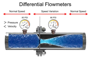
The differential flow meter is the most common device for measuring fluid flow through pipes. Flow rates and pressure differential of fluids, such as gases vapors and liquids, are explored using the orifice plate flow meter in the video below.

The differential flow meter, whether Venturi tube, flow nozzle, or orifice plate style, is an in line instrument that is installed between two pipe flanges.

The orifice plate flow meter is comprised the circular metal disc with a specific hole diameter that reduces the fluid flow in the pipe. Pressure taps are added on each side at the orifice plate to measure the pressure differential.

According to the Laws of Conservation of Energy, the fluid entering the pipe must equal the mass leaving the pipe during the same period of time. The velocity of the fluid leaving the orifice is greater than the velocity of the fluid entering the orifice. Applying Bernoulli's Principle, the increased fluid velocity results in a decrease in pressure.

As the fluid flow rate increases through the pipe, back pressure on the incoming side increases due to the restriction of flow created by the orifice plate.

The pressure of the fluid at the downstream side at the orifice plate is less than the incoming side due to the accelerated flow.

With a known differential pressure and velocity of the fluid, the volume metric flow rate can be determined. The flow rate “Q”, of a fluid through an orifice plate increases in proportion to the square root the pressure difference on each side multiplied by the K factor. For example if the differential pressure increases by 14 PSI with the K factor of one, the flow rate is increased by 3.74.

Guide to Industrial Electrical Grounding

Electrical Grounding
Acromag, a manufacturer of industrial I/O solutions, recently produced a 3-part series on the best practices of grounding electrical equipment. For your convenience, this post combines all three parts of the white paper here into a single document below.

When wiring or connecting circuits, electrical equipment, and electrical instruments, there is a connection that you probably don’t give much thought to, and one that consequently reigns as one of the greatest sources of instrument error and malfunction. That connection is Ground.

Electrical systems must be grounded in order to work properly. The earth often serves as an ideal ground because of its large mass and ability to absorb charge, but ground can be any electrical connection that is able to freely conduct electricity, and grounding a circuit does not always refer to making a physical connection to earth ground.

To learn much more, please read the following document.

Understanding Hot Tapping: Insertion Flowmeter Example

hot tapping insertion probe
Hot tapping insertion probe.
The ability to remove an insertion flowmeter probe is important for service and calibration. In many situations, it is not desirable to shut down the process and drain the pipe. In these cases, a method for removal known as "hot tapping" is preferred. Hot tapping (also known as pressure tapping) is a technique where a connection is made to an existing pipe or pressure vessel without disturbing flow or having to empty the pipe or vessel. This allows a pipe or tank to be in operation while maintenance or modifications are being done.

This video demonstrates the steps (and precautions) to remove a Seametrics flowmeter insertion probe from a live process (hot tap).  Insertion type flowmeters use a ball valve as the shut-off device and as isolation from the process media in the pipe. The video outlines the sequence of loosening the lock nut, raising the probe, then shutting off the valve before removal.


Additionally, here is a good document with more specific information on the insertion flow meter / hot tapping process:


For more information on any flowmeter installation, contact:

Instrument Specialties Inc.
3885 St. Johns Parkway
Sanford, FL 32771
phone 407.324.7800
fax 407.324.1104

Concepts of Process Instrument Calibration

Volumetric calibration rig
Measuring devices are an integral part of our lives nowadays, whether in everyday life or on the job. Take, for example, the scales at the supermarket check-out, the fuel volume measurement at the filling station pump, temperature measurement, velocity, flow volume and thermal energy, taxi meters etc. The wide variety of available quantities to be measured and measuring devices clearly illustrates the complex interplay between the quantity to be measured and the measuring device used. What does "accurate" actually mean in this context and how is this accuracy demonstrated? Why do we need accurate measuring devices?

Using the example of flowmeters, the following document will go into detail about these and other aspects of calibration and accuracy, and also looks at calibration standards from different countries around the world.


For more information regarding process instrumentation and calibration, contact:

Instrument Specialties Inc.

3885 St. Johns Parkway
Sanford, FL 32771
phone 407.324.7800
fax 407.324.1104
www.isisales.com

Lightning and Surge Protection for Potentially Explosive Atmospheres

Plant Lightning Protection
Protect your plant's hazardous area
from lightning strikes and surges
.
During producing, processing, storing and transporting flammable substances (e.g. fuel, alcohol, liquid gas, explosive dusts), potentially explosive atmospheres where no ignition sources may be present to prevent explosion frequently occur in chemical and petrochemical industrial plants. The relevant safety regulations describe the risk for such plants posed by atmospheric discharges (lightning strikes). In this context, it must be observed that there is a risk of re and explosion resulting from direct or indirect lightning discharge since in some cases these plants are widely distributed.

To ensure the required plant availability and safety, a conceptual procedure is required to protect parts of electrical and electronic installations of process plants from lightning currents and surges.

The white paper below, provided by DEHN,  provides an in-depth strategy on plant protection and safety from lightning strikes and surges in hazardous areas.


For more information, contact:
Instrument Specialties Inc.
3885 St. Johns Parkway
Sanford, FL 32771
phone 407.324.7800
fax 407.324.1104

The Valtek Control Valve: Understanding the Components

Valtek control valves
Flowserve (Valtek) control valves
Valtek control valves are also known for handling the most severe services: cryogenic, superheated steam, volatile and corrosive fluids, erosion, high pressure drops, vibration, cavitation, flashing, and high noise levels.

Valtek valves are equipped with spring cylinder or spring diaphragm actuators that provide the thrust and speed necessary to manage any service. Valtek four-way analog and digital positioners provide accuracy and response to handle the most exacting applications.

This video gives the viewer an understanding of the major components.


For more information, contact:
Instrument Specialties Inc.
3885 St. Johns Parkway
Sanford, FL 32771
phone 407.324.7800
fax 407.324.1104
e-mail: offices@isisales.com

Using Process Refractometers in the Processing of Sugar Cane

Sanitary process refractometer
(courtesy of K-Patents)
After sugar cane has been harvested, it must be processed in under 24 hours to avoid sugar loss by inversion to glucose and fructose. Traditionally, sugar cane processing requires two stages, milling and refining, but this two stages are slowly combining into on production facility. Process refractometers are commonly used to determine the concentration of a dissolved solids by making an optical measurement of a solution’s refractive index (nD).

In cane sugar refining and milling process, refractometers are used for accurate in-line Brix and concentration measurements with the purpose is to achieve high quality liquid and crystal sugars and to minimize costs of production. 

Specific uses of refractometers in sugar production are:
  • Optimize extraction process and to minimize usage of water that needs to be removed from sugar juice later at the evaporator stage.
  • Adapt product flow to the capacity of the evaporators in order to save energy.
  • Make sure that liquid bulk sugar and molasses meet specifications.
  • Control feed juice to adjust the concentration with the capacity of the separation columns. This leads to longer intervals between Recovering cycles and longer lifetime of the columns.
  • Monitor supersaturation over complete strike of crystallization.
  • Implement automatic and accurate seeding of the vacuum pan.
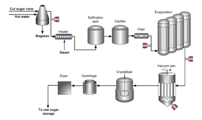
refractometers used in sugar production
Refractometers (in red) used in sugar milling


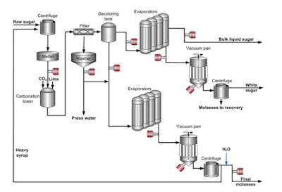
refractometers used in sugar production
Refractometers (in red) used in sugar refining


Download the complete Process Refractometer Application Note for Cane Sugar here.

For more information on process refractometers, contact:
Instrument Specialties Inc.
3885 St. Johns Parkway
Sanford, FL 32771
phone 407.324.7800
fax 407.324.1104
e-mail: offices@isisales.com