Using Process Refractometers in the Processing of Sugar Cane

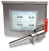
Sanitary process refractometer
(courtesy of K-Patents)
After sugar cane has been harvested, it must be processed in under 24 hours to avoid sugar loss by inversion to glucose and fructose. Traditionally, sugar cane processing requires two stages, milling and refining, but this two stages are slowly combining into on production facility. Process refractometers are commonly used to determine the concentration of a dissolved solids by making an optical measurement of a solution’s refractive index (nD).

In cane sugar refining and milling process, refractometers are used for accurate in-line Brix and concentration measurements with the purpose is to achieve high quality liquid and crystal sugars and to minimize costs of production. 

Specific uses of refractometers in sugar production are:
  • Optimize extraction process and to minimize usage of water that needs to be removed from sugar juice later at the evaporator stage.
  • Adapt product flow to the capacity of the evaporators in order to save energy.
  • Make sure that liquid bulk sugar and molasses meet specifications.
  • Control feed juice to adjust the concentration with the capacity of the separation columns. This leads to longer intervals between Recovering cycles and longer lifetime of the columns.
  • Monitor supersaturation over complete strike of crystallization.
  • Implement automatic and accurate seeding of the vacuum pan.
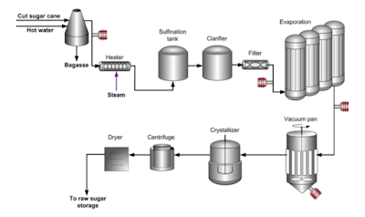
refractometers used in sugar production
Refractometers (in red) used in sugar milling


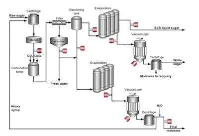
refractometers used in sugar production
Refractometers (in red) used in sugar refining


Download the complete Process Refractometer Application Note for Cane Sugar here.

For more information on process refractometers, contact:
Instrument Specialties Inc.
3885 St. Johns Parkway
Sanford, FL 32771
phone 407.324.7800
fax 407.324.1104
e-mail: offices@isisales.com
The Ins and Outs of Isolation: A Guide to Selecting The Right Instrument Isolator

Isolators
Isolators (courtesy of Acromag)
The primary function of the isolator is to eliminate ground loops that may exist between two or more instruments. A classic application isolates the control room equipment (computers, PLC, DCS etc.) from field devices which may have different ground potentials. In addition to break ing up ground loops, the isolators protect control room equipment from damaging transient spikes and noise generated in the field. Choosing the proper and most cost-effective isolator requires an understanding of the application and consideration of future expansion requirements.

Isolators are available in 2, 3, and 4 wire configurations. Isolators are further classified as input, output, or 3-way (input, output, power) isolators. Input isolation implies the input signal has no electrical connection to the output and power signals. Output isolation implies the output signal has no connection to the input and power. And similarly, 3-way isolation refers to a situation where there is no electrical path between the input, output, or power.


The technical paper below describes four types of isolators and typical PLC/DCS applications in which they are best suited. Each isolator produces a 4-20mA DC output signal corresponding to the 4-20mA DC input signal.

Variable Frequency Drives and Energy Savings: More Than Just Fan and Pump Applications

variable frequency drive
Siemens Medium Voltage Drive
When discussing energy savings and variable frequency drives (VFD) the attention often focuses on a centrifugal fan or pump application. However, you should not overlook other applications which also have large potential energy savings and energy recovery. Applications involving regeneration, power factor correction, common bus applications or a combination of the three can also quickly achieve a significant reduction in energy use.

The paper below provides detailed insight into other application areas where VFD's provide substantial energy savings.